In this article, we discuss how to interface the PIC microcontroller to various types of input and output devices. A key point to recall when dealing with PIC is that, each pin in the I/O ports may be configured in software as an input or an output. Furthermore, the port pins may be multiplexed with other functions to use additional features of the PIC.
In actual fact, the ports are different combinations of TTL and CMOS devices and have voltage and current limitations that must be factored in when interfacing with other devices to the PIC.
Interfacing Digital Inputs to PIC Microcontroller
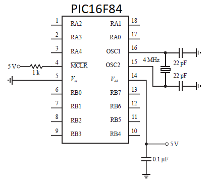
All I/O pins of the PIC that are configured as inputs interface through the TTL input buffer i.e. pins RA0 to RA3 and pins RB0 to RB7 or through the Schmitt trigger input buffer, for pin RA4. The Schmitt trigger boosts noise immunity for a slowly changing input signal. Since an input pin is TTL buffered in the PIC, interfacing a TTL gate or device to the PIC can be done directly unless it is has an open-collector output. In this case, an external pull-up resistor is needed. As the output of a 5 V powered CMOS device swings nearly from 0 to 5 V, the device will drive a PIC input directly.
The figure below, illustrates how to properly interface different types of components and digital families of devices as inputs to the PIC.

The weak pull-up option on pins RB0 to RB7 is useful using mechanical switches or keypads for input. The pull-up FET maintains a 5 V input until the switch is closed, bringing the input low. Even though a TTL input usually floats high if it is open, the FET pull-up option is useful, because it simplifies the interface to external devices such as keypad input. It is imperative to be aware of the current specifications of the PIC input and output pins. For instance, for the PIC16F84 microcontroller, there is a 25 mA sink maximum per pin with an 80 mA maximum for the entire PORTA and a 150 mA maximum for PORTB.
Interfacing Digital Outputs from PIC microcontroller
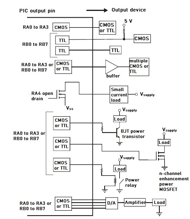
Pins RA0 to RA3 have full CMOS output drivers and RA4 has an open-drain output hence external components such as a pull-up resistor to power are required to complete the output circuit. RB0 to RB7 are TTL buffered output drivers. A 20 mA maximum current is sourced per pin with a 50 mA maximum current sourced by the entire PORTA and a 100 mA maximum for PORTB.
CMOS outputs can drive single CMOS or TTL devices directly. TTL outputs can drive single TTL devices directly but require a pull-up resistor to provide an adequate high-level voltage to a CMOS device. To drive multiple TTL or CMOS devices, a buffer can be used to provide adequate current for the fan-out. Since pin RA4 is an open-drain output, external power is required. Take note of the fact that, when RA4 is high, the output pin is grounded to Vss, switching the small current load ON, and when RA4 is low the output is an open circuit, switching the load OFF. Check the figure below, which illustrates how the digital outputs are interfaced to output devices.
When interfacing transistors, power transistors, and relays, current requirements must be put into consideration for a proper interface.
If the PIC contains a digital to analog (D/A) converter, it can be used with an amplifier to drive an analog load directly, If not, an external D/A IC can be used with the digital I/O ports.
Related articles:
Leave a Reply
You must be logged in to post a comment.